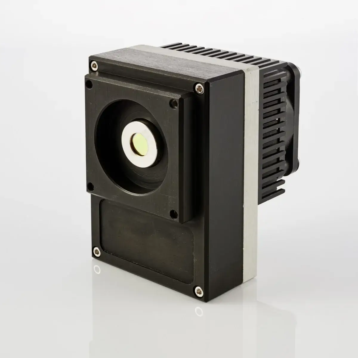
“All-in-one” transimpedance preamplifierAIP series
AIP is a new generation of transimpedance, AC or DC coupled preamplifiers. It is designed to operate with either biased or non-biased VIGO detectors. AIP is „all‑in-one” device – a preamplifier is integrated with a fan and a thermoelectric cooler controller in a compact housing. It is very convenient and user‑friendly device, thus can be easily used in a variety of applications.
Features
Integrated TEC controller and fan
Frequency bandwidth: up to 250 MHz
Single power supply
DC monitor
Designed for effective heat dissipation
Compatible with optical accessories
Cost-effective OEM version available
Types of VIGO detectors that can be integrated with AIP preamplifier
Photoconductive: PC-2TE, PC-3TE, PC-4TE
Photoconductive optically immersed: PCI-2TE, PCI-3TE, PCI-4TE
Photovoltaic: PV-2TE, PVA-2TE, PV-3TE, PV-4TE
Photovoltaic optically immersed: PVI-2TE, PVIA-2TE, PVI-3TE, PVI-4TE
Photovoltaic multi-junction: PVM-2TE
Photovoltaic multiple junction optically immersed: PVMI-2TE, PVMI-3TE, PVMI-4TE
Specification
(Tamb = 293 K)
Parameter |
Value |
Conditions, remarks |
|
| Low cut-off frequency, flo | DC, 10 Hz, 100 Hz, 1 kHz, 10 kHz | ||
|
High cut-off frequency, fhi
|
100 kHz, 1 MHz, 10 MHz, 100 MHz, 250 MHz | ||
|
Transimpedance, Ki
|
up to 200 kV/A | Fixed | |
|
Output impedance, Rout
|
50 Ω | ||
| Output voltage swing, Vout | ±1.8 V
±0.7 V |
fhi ≤ 1 MHz, Rload = 1 MΩ
fhi >1 MHz, Rload = 50 Ω |
|
|
Output voltage offset, Voff
|
max. ±20 mV*) | ||
|
Power supply voltage, Vsup
|
+5 V
+12 V |
With 2TE and 3TE cooled detectors
With 4TE cooled detectors |
|
| Power supply current, Isup | max. 1.2 A
max. 0.5 A max. 0.45 A |
With 2TE cooled detectors
With 3TE cooled detectors With 4TE cooled detectors |
|
|
Ambient operating temperature, Tamb
|
10 to 30ºC | ||
|
Signal output socket
|
SMA | RF output | |
|
DC output socket
|
SMA | DC monitor | |
|
Supply socket
|
DC 2.1/5.5
DC 2.5/5.5 |
Vsup = +12 V
Vsup = +5 V |
|
|
Mounting hole
|
M4 | ||
|
Built-in fan
|
yes | ||
|
Built-in TEC controller
|
yes | ||
|
*) Measured with equivalent resistor at the input instead of the detector, it is to avoid the environmental thermal radiation impact.
|
|||
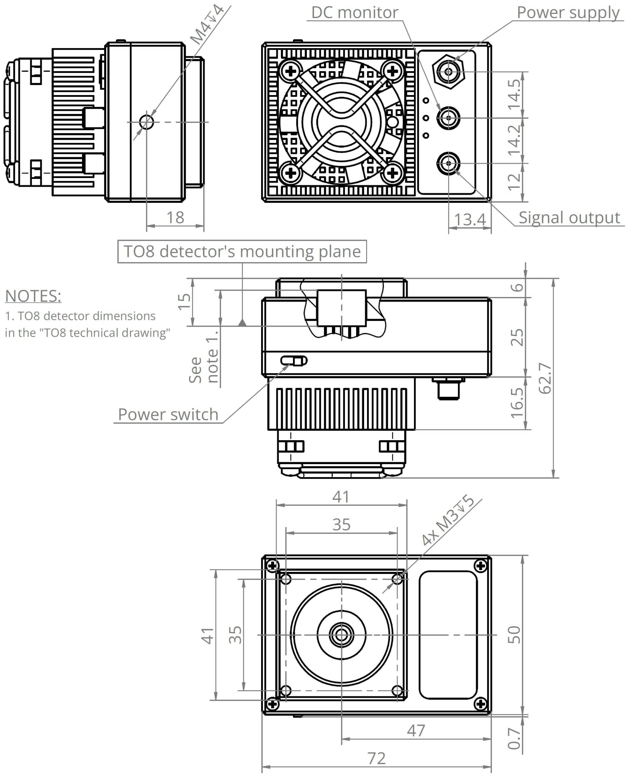
Mechanical layout
(Unit: mm)

Access to file
Access to this file is limited. In order to download it, please provide all the information and submit the form.
Application notes

Temperature sensor characteristics


Dedicated accessories
Contact form
For more information, please contact us directly: