Photodiode vs photoresistor – which IR detector to choose?

Infrared photon detectors can operate on one of two principles: either they are a photodiode or a photoresistor. On the first glance, one may think that there is no difference from the user's point of view – but there are a lot of nuances which may decide in favor of or against using a particular device, photodiode vs photoresistor, in each application.
This guide will show you specific features of both photovoltaic and photoconductive IR detectors and advantages vs drawbacks of each type. With this knowledge, you should be able to make a more informed decision about the infrared sensor to suit your needs.
First step is to understand the principles of operation of photodiodes and photoresistors – since a lot of their features stem directly from their design.
How does a photoresistor work?
Historically photoresistors, known also as photoconductive detectors (PC), were the first to appear, since design-wise, they are much simpler devices to manufacture. Thanks to that, PC detectors are known to be stable and reliable, with excellent lifetime and MTBF. They are photon detectors – means one absorbed photon of IR radiation equals one pair of electrical carriers generated in the semiconductor structure. In a PC detector, this incident radiation changes the properties of the structure – namely, its resistance (hence the name). For that reason, the Photoconductive detector needs to be connected into the electrical circuit with current flowing through it, so that the user can register said resistance changes. Depending on the preferences, photoresistors can be biased with constant current (meaning voltage signal will appear on the load resistor) or constant voltage (which results in current signal) – though more popular and recommended is the constant current mode of operation. Unfortunately, this bias means the presence of 1/f noise at low frequencies (usually below 10 kHz or lower), which combined with overall low speed of operation limits the effective bandwidth of these devices. PC detectors exhibit constant base resistance independently of active area size (for square-shaped structures), so relatively big active areas are possible. Conversely, too small active areas (i.e. below 200x200um2) are prone to saturation. Finally, the spectral response of photoresistors is broad and smooth in shape – more uniform for different wavelengths (although not completely the same).
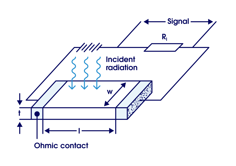
1. Principle of operation of IR photoresistor, source: A. Rogalski, Infrared Detectors, CRC Press, Boca Raton, FL, Second edition, 2011
How does a photodiode work?
Photodiodes, known also as Photovoltaic (PV) IR detectors, have been steadily gaining in popularity since their entrance to the market. They rely on a slightly more complex structure – a diode p-n or p-i-n junction. When light is absorbed, the created electron-hole pair moves to their respective electrodes and this results in a photocurrent – so an electrical signal.
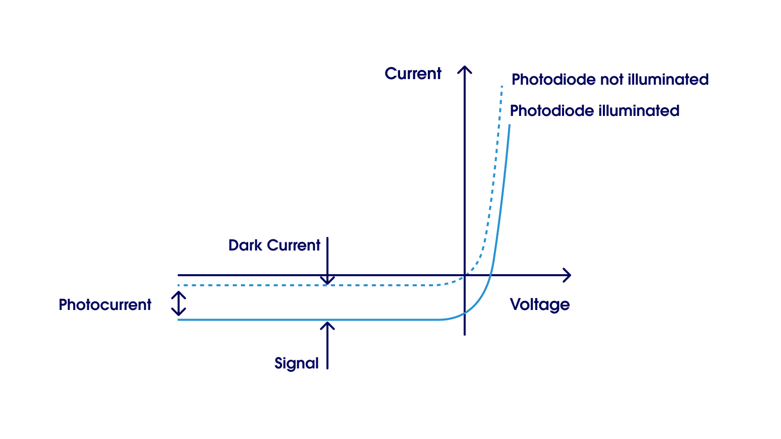
2. I-V characteristics of IR photodiode
In principle, PV detectors do not have to be biased – which is especially true for MIR photodiodes such as those made by VIGO, with HgCdTe or T2SL absorbers. This reduces noise level, complexity of electronic circuitry, as well as power consumption. No bias means also almost no 1/f noise – making PV detectors perfect for DC or low-frequency operation. Reverse bias, though, remains an option – used here mainly to increase the bandwidth of the devices, even up to single GHz in some cases (compared to tens of MHz without reverse bias). The main drawbacks are: limited spectral response (with sharp cut-on and cut-off slopes) and relatively small active area sizes. This is tied to the property of the photodiodes that the active area length-resistance product remains constant – meaning that the shunt resistance of the photodiode will drop with increasing size to the point of inusability. Effectively, this limits the active area size to anywhere between 1x1 mm for InAs diodes down to 0.1x0.1 mm2 for LWIR HgCdTe. Shunt resistance may be increased by cooling a detector, while optical immersion increases the apparent optical area of the photodiode. Both goals can also be achieved with a multi-junction layout of the photodiode, which can be realized in multiple ways. The reliability of PV detectors has increased since the first devices and is now only slightly worse than for photoconductive detectors – while detectivity remains consistently very high, even approaching in some cases the theoretical limits.
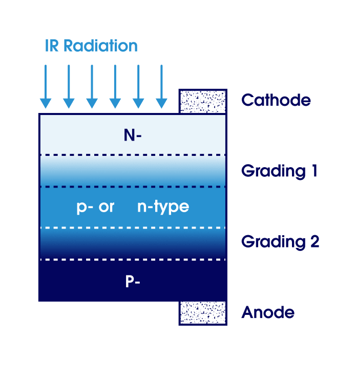
3. Principle of operation of IR photoresistor, Source: A. Rogalski, Infrared Detectors, CRC Press, Boca Raton, FL, Second edition, 2011
Summary of the comparison of photodiodes vs photoresistors
To sum up the advantages vs disadvantages of photodiodes vs photoresistors, we have created a cheat sheet to help you decide which detector type should better fit your needs.
| Photodiodes (photovoltaic, PV) | Photoresistors (photoconductive, PC) | |
| Features | • Spectral range suited for highest detectivity • No 1/f noise without bias • Reverse bias possible to increase bandwidth • Immersion lens possible • TE cooling possible • Multi-junction layout possible |
• Broad spectral ranges • High detectivity • Require bias • Current or voltage mode of operation • Immersion lens possible • TE- or LN2-cooling possible |
| Advantages | • Very high detectivity • Lower noise level • Fast operation, high bandwidth • Low power consumption without bias |
• Excellent reliability and stability • Long lifetime and MTBF • Big active areas possible • High detectivity |
| Disadvantages |
• Limited active area size (if single-junction) • Reverse bias introduces 1/f noise |
• 1/f noise on lower frequencies • Low speed overall |
Q&A Section
Question 1: What is the difference between photodiode vs photoresistor?
These devices differ in the design and construction, as they function on different principles of operation from an electrical point of view. IR photodiode is usually a PIN junction, which only generates dark current when not illuminated, and a complete signal during illumination with IR radiation. IR photoresistor on the other hand is constantly biased, and illumination changes only the value of resistance of this element.
Question 2: What are the main advantages of a photodiode?
IR photodiodes offer very high detectivity thanks to low noise (including intrinsically no 1/f noise). No bias requirement means also low power consumption. Additionally, photodiodes are well suited for extremely fast operation - even above 3 GHz for LWIR photodiodes.
Question 3: What are the main advantages of a photoresistor?
IR photoresistors boast relatively big active areas and excellent reliability and MTBF. They also offer very broad spectral ranges, making them ideal for applications which require detection of numerous wavelengths with a single detector. The spectral response curve is also relatively flat, meaning that response to different wavelengths will be similar.
Author: Jędrzej Mijas, Application Engineers Team Lead, VIGO Photonics
References:
- Rogalski, Infrared Detectors, CRC Press, Boca Raton, FL, Second edition, 2011