“All-in-one” IR detection module based on an HgCdTe room-temperature photovoltaic multi-junction quadrant detectorQM-10.6-01
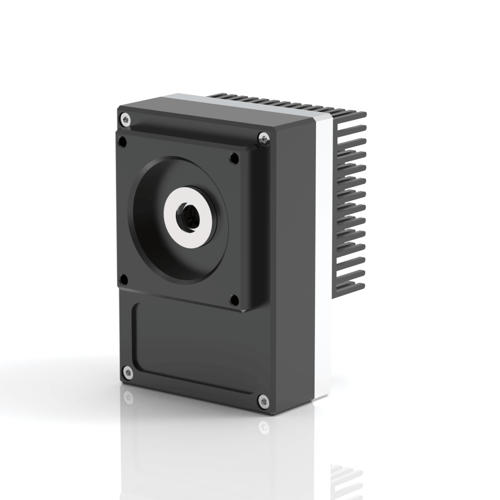
QM-10.6-01 is an “all-in-one” infrared position detection module. An uncooled photovoltaic multi-junction quadrant detector (PVMQ-10.6-1x1-TO8-NW-70), based on a HgCdTe heterostructure, is integrated with a DC-coupled four-channel transimpedance amplifier in a compact housing. The module features an integrated offset calibration function to ensure high measurement stability.


Features
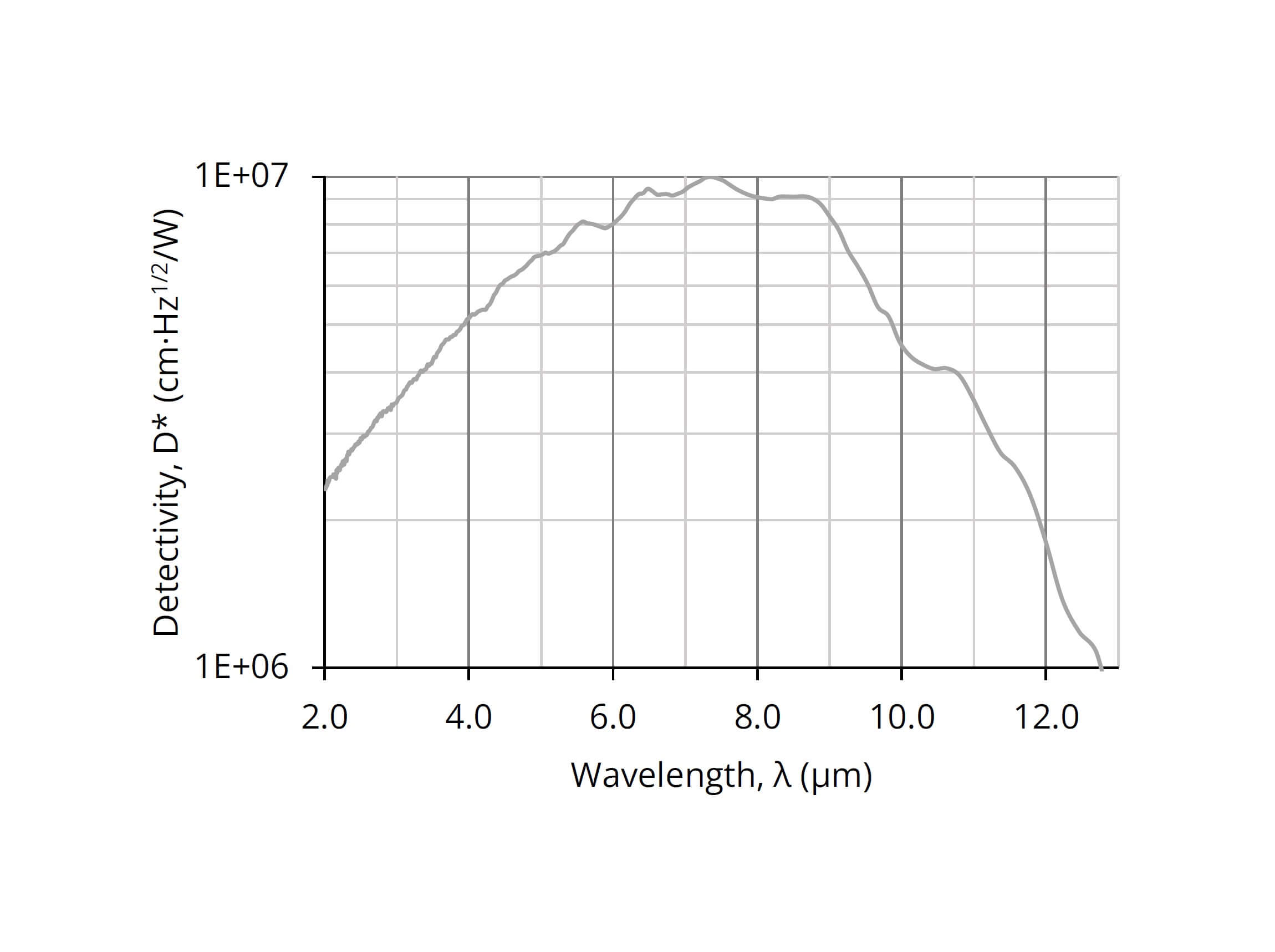
Spectral range: 2.0 to 12.0 µm
Frequency bandwidth: DC to 1.0 MHz (typ.)
Low crosstalk
M4 mounting hole
Single power supply
Switchable offset calibration modes via protected hardware button
Optional 0 to 3 V voltage swing modification available upon request for direct ADC compatibility
Compatible with optical accessories
Detector and detector chip options available for custom integration
Applications
Gas detection, monitoring and analysis: SO2, NH3, SF6
CBRN threats detection
CO2 laser measurements: power monitoring and control, beam profiling and positioning, calibration
Free-space optical communication
FTIR spectroscopy
Dentistry
Detection module configuration
| Detection module symbol | QM-10.6-01 |
| Detector symbol | PVMQ-10.6-1x1-TO8-NW-70 |
| Detector type | photovoltaic, multi-junction |
| Active element material | epitaxial HgCdTe heterostructure |
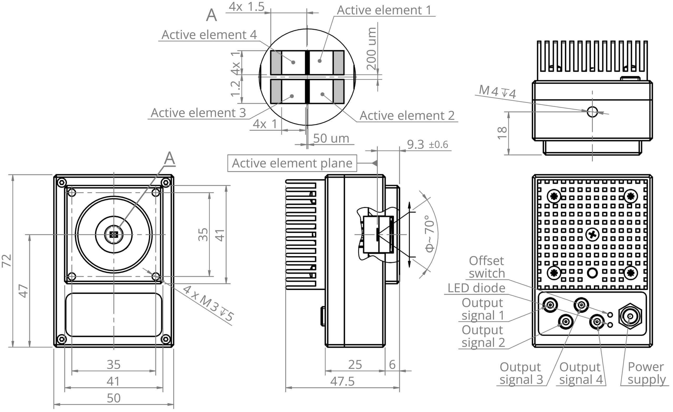
| Active area of a single element, A | 1 mm × 1 mm |
| Number of elements | 4 (2 rows, 2 columns) |
| Active area pitch, mm | 1.15 (horizontally)
1.20 (vertically) |
| Optical immersion | no |
| Cooling | no |
| Temperature sensor | n/a |
| Acceptance angle, Φ | ~70 deg. |
| Window | no |
| Amplifier type | four-channel, transimpedance |
| Signal output socket | 4 x MCX |
| Power supply socket | DC 2.1/5.5 |
Specification
(Tamb = Tchip = 293 K, Rload = 1 MΩ, each channel)
| Parameter | Test conditions, remarks | Value | Unit | ||
| Min. | Typ. | Max. | - | ||
| Active element temperature, Tchip | Tchip=Tamb | - | ~293 | - | K |
| Cut-on wavelength, λcut-on (10%) | At 10% of the peak responsivity | - | 2.0 | - | µm |
| Peak wavelength, λpeak | - | 8.5±1.0 | - | µm | |
| Specific wavelength, λspec | - | 10.6 | - | µm | |
| Cut-off wavelength, λcut-off (10%) | At 10% of the peak responsivity | - | 12.0 | - | µm |
| Detectivity, D* | At λ=λpeak, f=100kHz
At λ=λspec, f=100kHz |
-
- |
1.0×10⁷
8.0×10⁶ |
-
- |
cm×Hz1/2/W |
| Output noise voltage density, vn | At f=100kHz | - | - | 4.5 | μV/Hz1/2 |
| Voltage responsivity, Rv | At λ=λpeak
At λ=λspec |
-
- |
3.0×10²
2.0×10² |
-
- |
V/W |
| Low cut-off frequency, flo | DC coupling | - | 0 | - | Hz |
| High cut-off frequency, fhi | - | 1.0 | - | MHz | |
| Output impedance, Rout | - | 50 | - | Ω | |
| Output voltage swing, Vout | - | 0-4 | - | V | |
| Output voltage offset, Voff | - | - | ±20 | mV | |
| Power supply voltage, Vsup | +6 | - | +12 | VDC | |
| Power supply current consumption, Isup | - | 70 | 230 | mA | |
Spectral response
(Typ., Tamb = Tchip = 230 K, each channel)
Mechanical layout (unit: mm)

Access to file
Access to this file is limited. In order to download it, please provide all the information and submit the form.

Application notes

Temperature sensor characteristics


Dedicated accessories



For more information, please contact us