Programmable IR detection module based on InAsSb thermoelectrically cooled optically immersed photovoltaic detectorLabM-I-13
LabM-I-13 is a detection module featuring a TE-cooled, optically immersed photovoltaic IR detector based on an InAsSb heterostructure (PVIA-4TE-13-1x1-TO8-wZnSeAR-36), integrated with a programmable, transimpedance amplifier (PIP series).
For proper operation, the VIGO programmable thermoelectric cooler controller PTCC-01 (sold separately) and Smart Manager Software (freeware) are required.
The LabM-I-13 detection module comes complete with PTCC-01 and Smart Manager Software, making it the best solution for prototyping and the R&D stage in various LWIR applications. This set provides a flexible approach to the different needs of system designers.

Features
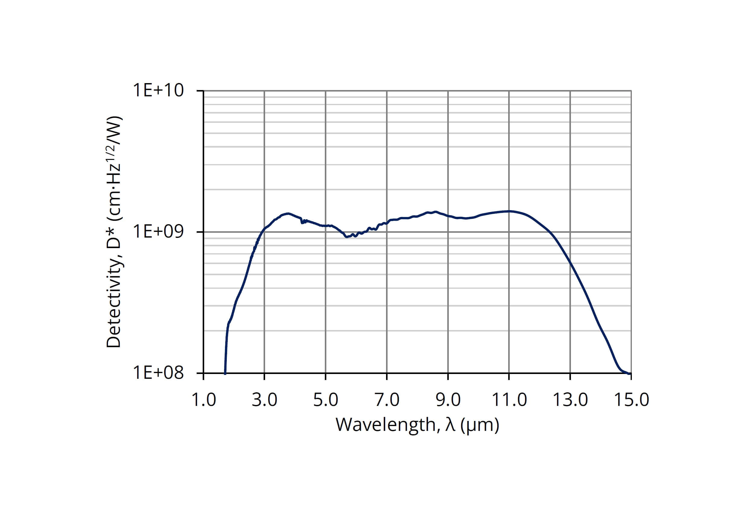
Spectral range: 1.8 to 13.8 µm
RoHS-compliant III-V material
Frequency bandwidth: DC to 75 MHz (typ.)
High performance and reliability
DC offset compensation
Integrated fan
M4 mounting hole
VIGO PTCC-01 TEC controller obligatory
Compatible with optical accessories
Versatile and flexible
Quantity discounted price
No minimum order quantity required
Applications
FTIR spectroscopy
Gas detection, monitoring and analysis: C2H6
Toxic gas detection
Gas leak detection
Detection module configuration
| Detection module symbol | LabM-I-13 |
| Detector symbol | PVIA-4TE-13-1x1-TO8-wZnSeAR-36 |
| Detector type | photovoltaic |
| Active element material | epitaxial InAsSb superlattice heterostructure |
| Optical area, Ao | 1 mm × 1 mm |
| Optical immersion | hyperhemisphere |
| Cooling | 4TE (Tchip≅200K) |
| Temperature sensor | thermistor |
| Acceptance angle, Φ | ~36 deg. |
| Window | wZnSeAR (3 deg. wedged zinc selenide, anti-reflection coating) |
| Amplifier symbol | PIP |
| Amplifier type | programmable, transimpedance |
| Signal output socket | SMA |
| Power supply, TE cooler, thermistor and fan socket | LEMO ECG.0B.309.CLN (female) |
Specification
(Tamb = 293 K, Tchip = 200 K, Rload = 50 Ω, unless otherwise noted; default module settings)
| Parameter | Test conditions, remarks | Value | Unit | ||
| Min. | Typ. | Max. | - | ||
| Active element temperature, Tchip | - | 200 | - | K | |
| Cut-on wavelength, λcut-on (10%) | At 10% of the peak responsivity | - | 1.8 | - | µm |
| Peak wavelength, λpeak | - | 10.5 | - | µm | |
| Cut-off wavelength, λcut-off (10%) | At 10% of the peak responsivity | - | 13.8 | - | µm |
| Detectivity, D* | At λ=λpeak, f=10MHz | - | 1.4×10⁹ | - | cm×Hz1/2/W |
| Output noise voltage density, vn | At f=10MHz | - | 450 | - | nV/Hz1/2 |
| Voltage responsivity, Rv | At λ=λpeak | - | 6.5×10³ | - | V/W |
| Low cut-off frequency, flo-DC | DC coupling selected | - | 0 | - | Hz |
| Low cut-off frequency, flo-AC | AC coupling selected | - | 10 | - | Hz |
| High cut-off frequency, fhi-H | High bandwidth selected | - | 75 | - | MHz |
| High cut-off frequency, fhi-M | Mid bandwidth selected | - | 15 | - | MHz |
| High cut-off frequency, fhi-L | Low bandwidth selected | - | 1.5 | - | MHz |
| Output impedance, Rout | - | 50 | - | Ω | |
| Output voltage swing, Vout | - | - | ±1 | V | |
| Output voltage offset, Voff | - | - | ±20 | mV | |
| Power supply voltage (positive), +Vsup | - | +9 | - | V | |
| Power supply voltage (negative), -Vsup | - | -9 | - | V | |
| Power supply current consumption (positive), +Isup | - | - | +100 | mA | |
| Power supply current consumption (negative), -Isup | - | - | -100 | mA | |
| Fan power consumption, Pfan | - | - | 900 | mW | |
| TEC voltage, VTEC | - | - | 8.3 | V | |
| TEC current, ITEC | - | - | 0.4 | A | |
| Weight | - | 180 | - | g | |
Spectral response
(Typ., Tamb = 293 K, Tchip = 200 K)
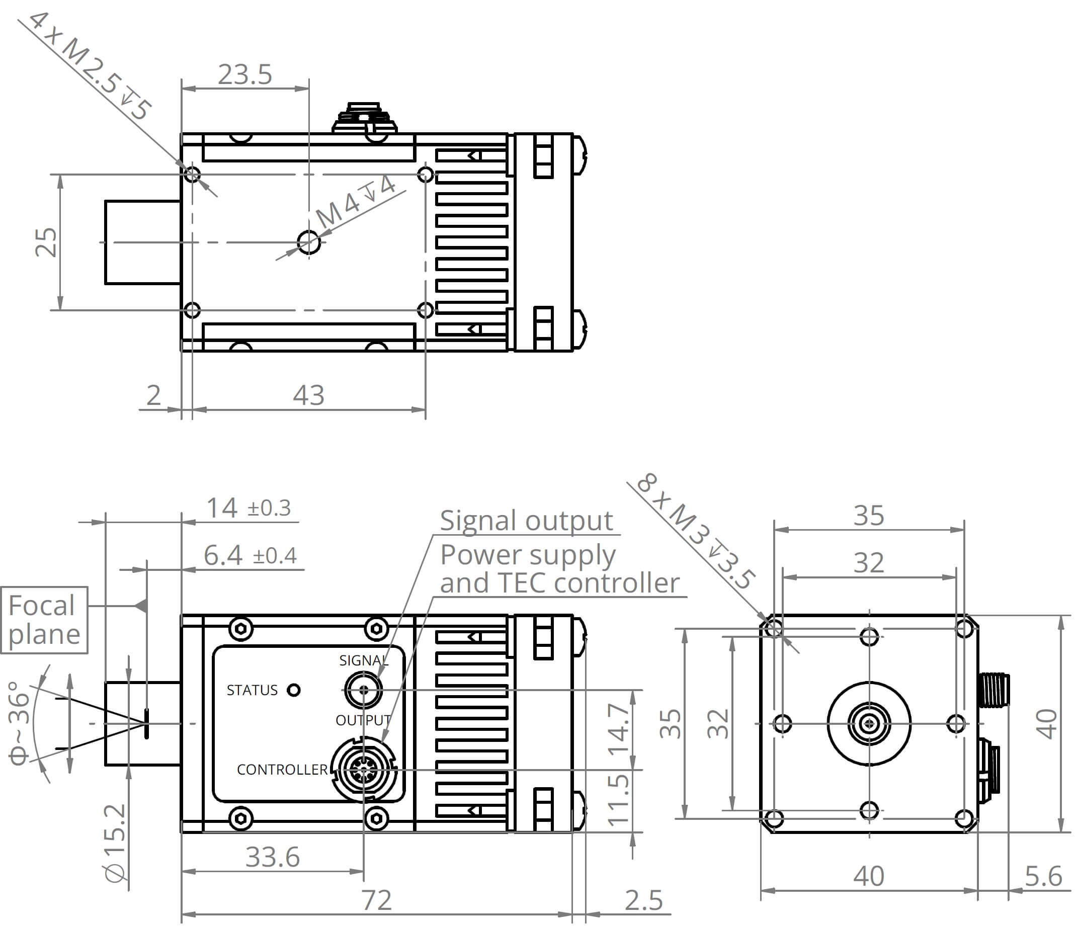
Mechanical layout (unit: mm)
Access to file
Access to this file is limited. In order to download it, please provide all the information and submit the form.
Application notes
![]()
Temperature sensor characteristics


For more information, please contact us