Optimizing IR Detectors for TDLAS Gas Sensing Systems

For the ultimate performance of an infrared gas sensor, one must swap out a thermal light source for a laser. Combining such a light source with appropriate optics, detector and signal processing techniques is what makes a typical gas sensor using Tunable Diode Laser Absorption Spectroscopy (TDLAS). It is one of the most powerful gas sensing techniques and always requires a high-performance IR detector.
Understanding TDLAS Techniques
TDLAS, as the name implies, uses diode lasers, usually quantum cascade or interband cascade laser type (QCLs/ICLs), and their tunability around a specific wavelength absorbed by a gas of interest. At its core, it is a relatively simple setup, but reduction of the limit of detection (LoD) of a TDLAS gas sensor requires the use of specific techniques concerning the tunability and modulation of the laser, as well as manipulating the optical path of the IR radiation through the gas sample.
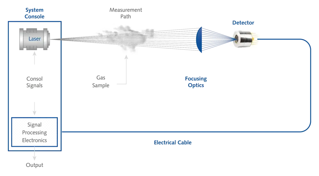
Figure 4. Layout of a typical TDLS setup. System console used for controlling light source and detector readout is clearly visible.
Wavelength Modulation Spectroscopy (WMS) or Frequency Modulation Spectroscopy (FMS) are ways to combat random noise showing up in the system, and as absorption of the gas depends on the length of optical path, an extractive system with a multi-pass cavity may be designed to extend the path. All of these techniques pose challenges to a most vital component of the gas sensor: an IR detector. However, some of the requirements stay true regardless of the design of the sensor, while others are specific for a given technique.
Understanding the Impact of Detector Parameters
The most obvious parameter which has to be suited to the system is the wavelength response of the detector. As a laser light source - even when tunable- is relatively narrow-band compared to other types of light sources such as LEDs or thermal, this simplifies the choice of the detector.
However, one may be tempted to choose a detector based on their peak response of detectivity - but it is not so obvious. Usually it is recommended to choose a detector for which the wavelength of interest lies slightly before the wavelength for which the response starts to drop (which may or may not coincide with peak wavelength). This ensures better behaviour with tunable lasers (flatter shape of detectivity spectral curve) and less susceptibility to fringing effect inside the detector chip (described in more detail below).
Bandwidth and Detectivity
Time constant, translating directly to detection module’s electrical bandwidth, is also an important parameter here, but most modulation techniques result in a registered signal being of frequency below 1 MHz, which lies well within the possibilities of most photovoltaic IR detectors. This also ensures real-time measurements being possible, a feature especially useful in gas sensors used for continuous process control or leak detection.
Detectivity becomes important for TDLAS variations with very faint signals or very slight variations thereof, e.g. multi-pass systems, where an optical path of tens to hundreds of meters means that optical power reaching the detector is really low, especially after absorption by the gas of interest. The laser beam there is usually focused and pointing the same way all the time.
On the other end of the TDLAS spectrum we have so-called open-path systems, sometimes deployed in the field, which are prone to misalignment of the laser beam or just limited accuracy of pointing due to physical constraints and tolerances of the place of deployment. For that, big active areas start playing an important role rather than especially good detectivity - simply for the ease of pointing light to the detector. Losses in limit of detection of the gas sensor resulting from “worse” detectors may then be compensated by more sophisticated modulation/demodulation techniques. Regardless of the place of usage, TE-cooled or temperature-stabilized detectors are recommended to keep the background noise floor at the same level.
Addressing Unique TDLAS Challenges
High Linearity Requirements
The above discussed parameters are some of the most commonly mentioned in detectors’ datasheets. However, TDLAS systems are quite nuanced when it comes to the detector choice and apart from what was mentioned before, there are two issues which are very visible in TDLAS systems.
First is the requirement for high linearity of the detectors. Some modulation techniques or detection schemes may have the optical power coming to the detector vary wildly during the course of operation. Also, ensuring a broad dynamic range of the gas sensor - i.e. range of gas concentrations detected by the sensor—may have similar results, as high concentrations will absorb more IR radiation. Linear behaviour of the detector reduces necessary steps in signal processing, allowing the electronics to skip the nonlinearity compensation step and eliminate the need for pre-calibration. For the sake of linearity, optically immersed detectors are generally not recommended as they exhibit poorer linearity behaviour - but may still be used where there are very low optical powers involved (e.g. precise multi-pass measurements of extremely low concentrations).
Combatting the Etalon Effect (Fringing)
The second and very prominent issue is related to the so-called fringing, also known as etalon effect. The principle here is that in the optical system, each pair of parallel surfaces can act as an etalon, meaning that when illuminated with coherent light (such as laser light), the transmission coefficient will vary significantly with slight changes of the wavelength. This results in the sine-like modulation (“fringes”- hence the name) of the intensity vs wavelength function and of course introduces unwanted baseline noise in TDLAS systems with their tunable light sources.
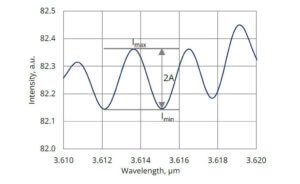
Figure 1. Optical fringing effect
Distance between the parallel surfaces determines the period between the peaks of light intensity and so some etalons in the TDLAS systems may coincide with the modulation/tunability range of the laser source. Thanks to specific modifications, it is possible to remove the influence of etalons inside the detector package, where there are plenty of possibilities to introduce fringing - window, distance between the window and detector chip, and even the chip itself!
To combat this, VIGO has introduced a dedicated anti-fringing detector which features wedged window, wedged housing as well as special preparation of detector chip surfaces - all for the ultimate performance in the demanding TDLAS systems.
Learn more about Anti-Fringing technology in our Technical Note
Author: Jędrzej Mijas, Application Engineer Lead
Contact our Technical Support team for specific information on our capabilities.